What's new
What's new

5hp Single Phase Motor Not Running When Wired for Reverse

micro

Stainless
Joined
Jan 26, 2005
Location
NYC
Apologies if this isn't quite the right forum for this post.

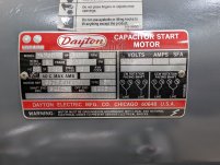
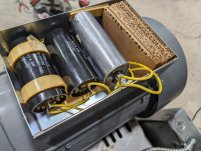
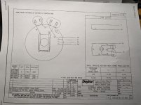
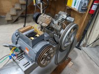
I just got an NOS Dayton, 5 horsepower, 1730RPM single phase motor that was sitting on a shelf for the last 10 years. It is to replace the aging 3 phase OEM motor so that I don't have to have the phase converter on to keep the compressor at pressure. I mounted it to the tank and wired it (2 phases, #8awg from 35a breaker). I wired it for CCW rotation (T1-T5, T4-T8) as per the panel on the motor. When I switch it on with no load it buzzes (60hz) very loudly and the shaft turns slowly. If I wire it CW Rotation (T1-T8, T4-T5) by swapping 2 of the 4 wires coming out of the motor, It runs beautifully. I Called Grainger (dayton) and they were little help. They emailed me 2 schematics which confirm that I have it wired correctly, but the prints are for a later revision and seem to have a slightly different Capaciotor configuration for the start and run Caps. If it is running fine in one direction, doesn't this mean the windings are intact? Can any one offer some trouble shooting guidance?
(yes I know to discharge the caps before handeling them.) :)
PXL_20240125_042422850.jpgPXL_20240124_012146871.jpgPXL_20240125_042432368.jpg
 
Sure sounds like your start winding is not coming on after your rewire. #5&8 are normally the start winding circuit, I would double check your connections there.

If it works in one direction, one would think it should run the opposite direction if effectively connected.

The only other thing I could think of would be the centrifugal start switch or the start capacitors connections being distributed during reconnection.

Loud buzzing is the run winding energized without a start winding to kick it in the proper direction.
 
Motor caps are connected across motor windings and thus discharge through the windings. Normally no need to worry about charged-up caps.
 
Motor caps are connected across motor windings and thus discharge through the windings. Normally no need to worry about charged-up caps.
I noticed they also have bleed off resistors across the terminals. Better safe than sorry though.
 
Sure sounds like your start winding is not coming on after your rewire. #5&8 are normally the start winding circuit, I would double check your connections there.

If it works in one direction, one would think it should run the opposite direction if effectively connected.

The only other thing I could think of would be the centrifugal start switch or the start capacitors connections being distributed during reconnection.

Loud buzzing is the run winding energized without a start winding to kick it in the proper direction.
Thank you. This is very useful in helping me understand how these capacitor start/run motors work. Looking at the schematic again, it now makes more sense to me. I've connected the motor in CCW config at least 4 times making sure all the wires have a good connection and still the same problem. there must be something in either the connections to the start windings or capacitors.

This is the schematic Dayton sent me. It is slightly different as my motor has 3 caps (2 wired in series) and some of the wires are numbered differently, but they seem to go to the same places. I'll trace them to be sure and put a meter on them to make sure there isn't an open circuit. PXL_20240125_164328460.jpg
 
Makes no sense. All you are doing is reversing the start windings (5&8) to the motor. As long as the centrifical switch is making contacts, it should start either direction.
 
Update: I checked the continuity of the windings with a multimeter and ultimately found that T8 had a short somewhere in the motor body. It wasn't a short to ground, but there was continuity between T8 and T1 and T4. The short. must have been after the star. winding because T5 didn't have this continuity, and the motor would start when wired CW rotation. I called a local motor repair place and was told that going into the windings to try to fix it wasn't realistic. I'm going to find a 3Φ replacement motor, and get a VFD eventually so I can run it in stand by on single phase and keep the phase perfect off.
Anyone need a 5hp motor that only runs clock wise? :)
 
Sounds like it was purpose made to start in that one direction. Not uncommon for motors with no need to reverse, it's cheaper to connect in the factory.

Also possible that the motor will go both ways if it has a 230V connection. The reversing winding might connect to the join between the two coils in high voltage connection. Then changing from 1 to 4 on the end that you have, would reverse the start. A bit tricky to identify that, unless you ohmmeter will read accurately at the low end of the scale so that you can ID a direct connection vs a couple of ohms reliably.

It IS possible to find the end of the winding, and disconnect it to bring out that connection, if you dig in. Normally it is on the end of the windings somewhere. Unlikely that it is buried under other coils. Might not be worth it if the motor is easily replaced.
 
The nameplate pretty clearly shows both CW and CCW rotation, so unless the actual nameplate is wrong it seems unlikely.

Does sound like an odd fault.
 
Indeed you are correct, I did not go back and look.... my bad.

I have been trying to figure out how I would make that happen if I wanted it to. Seems as if it has to be shorted to one of the motor wires.

An ohmmeter would find that, disconnect both 5 and 8, then check for continuity to the run winding. If you find continuity, then yes there is a short somewhere.
 
Just for confirmation, I drove it down to the motor shop. They put it on the bench, and confirmed the problem I was having. They ohmed the windings, and determined that T8 was in fact, shorted to one of the Primary windings. We opened it up and took a quick look, but couldn't see an easy fix. It figures. I would have the one problem that either the factory guys nor the motor shop had ever seen before. Hopefully this thread will come up in a search if somebody else has this problem has this problem in the future.
 
Somebody knew before, likely why it was 10 year vintage NOS. Good on you for figuring it out. That start winding would eventually get worse even if it was used in the direction that still works.

Using it for reciprocating compressor starting duty would finish it off even sooner.
 
L1 AND L2 ARE YOUR POWER WIRES

t1 and t4 are your single phase power winding. it is a single phase motor, says on the tag. T5 or T8 CONNECT TO A CENTRIFUGAL START SWITCH through the start winding. you can reverse t5 and t8 with your switch to reverse the motor.


FOR 230V
CONNECT; LI TO T1
T5 TO T4.
T8 TO L1


120VAC

if you can find t2 and t3, you can use 120v by connecting t1 and t3 to line1.
t2 and t4 to each other and to t5
connect T8 to L2 (YOUR OTHER LINE)

to reverse rotation in either case, reverse t5 and t8. be sure the capacitors are wired as in the schematic above
 
Somebody knew before, likely why it was 10 year vintage NOS. Good on you for figuring it out. That start winding would eventually get worse even if it was used in the direction that still works.

Using it for reciprocating compressor starting duty would finish it off even sooner.
I MADE A MISTAKE
CORRECT WIRING

230V
L1 TO T1 TO T5
L2 TO T4 TO T8

120V
LI TO T1 TOT3 TO T5
L2 TO T2 TO T4 TO T8

SWAP T5 AND T8 IN EITHER CASE TO REVERSE IT


Back
Top